16.8. High voltage#
| Author: | Leo te Brinke |
| Time: | 30-50 minutes |
| Age group: | Grade 10 and up |
| Concepts: | Transformer, electrical power, voltage division, replacement resistance |
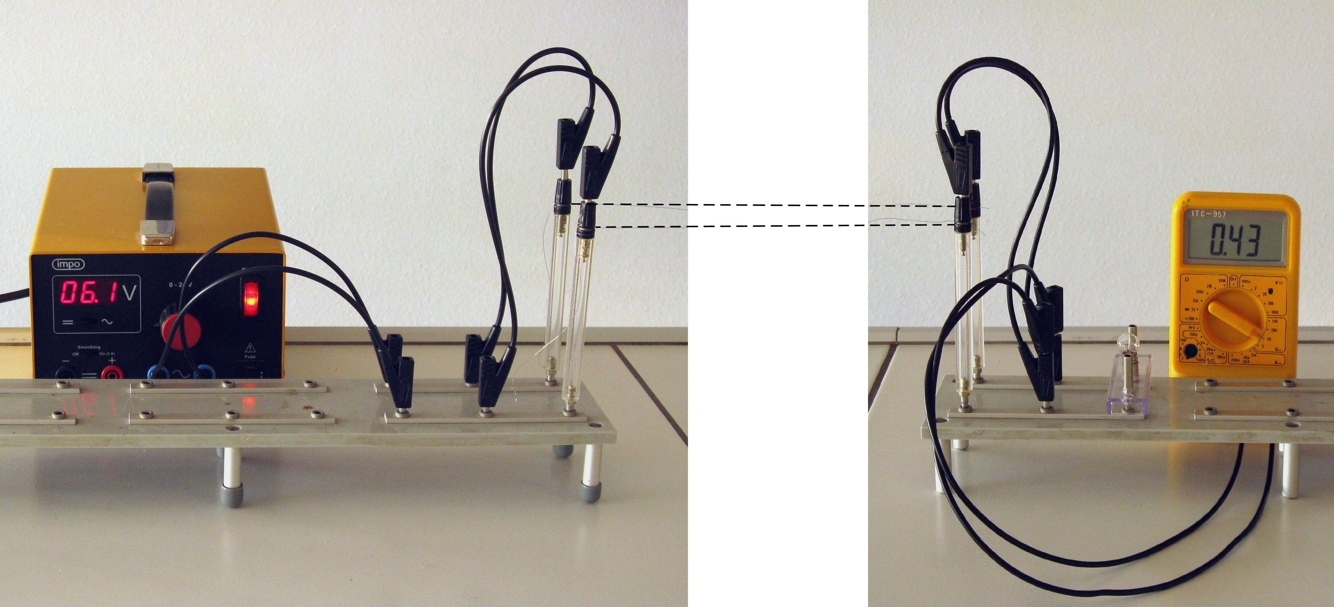
Fig. 16.22 No light without transformer#
Introduction#
A complicated but thorough demonstration showing that electrical energy transport is more efficient at high voltage. Besides the transformer, almost all basic concepts of electricity are discussed.
Warning
In simple form, this experiment can also be used in junior school, without too much theory, to show that transforming can be useful. This demonstration cannot be carried out as a student practical because the ‘high-voltage line’ can carry more than 40 V AC voltage, which can be dangerous.
Know that this demonstration is carried out in the Netherlands (230V, DC)!
Equipment#
Two demonstration transformers with, if possible, the same transformation ratio (e.g. 50 : 600), or two (preferably equal) mains adapters or bell transformers
AC power supply (0-30 V)
AC current meter(s) (range at least 0.5 A)
AC voltage meter(s), preferably digital with not too small digits (range depends on the transformers, maybe 500 V)
Bulb (e.g. 6 V;0.5 A) in socket
Long thin wires with a resistance preferably a bit larger than that of the burning bulb (constantan wire 0.20 mm will do)
Plug pins and switching or tripod material to build the ‘high-voltage line’
Various cords, including some very long ones
Preparation#
Build a ‘high voltage line’ from the two thin wires, 1.5-2 m long (if the demonstration table allows).
Connect the power supply at one end (AC voltage!) and the light bulb at the other.
Connect a voltage meter to the source.
If necessary, prepare a second voltage meter with long cords (must be able to span the length of the high-voltage line).
Get the two transformers ready in such a way that they can be incorporated into the circuit in no time.
Prepare two cords as long as the transmission line.
Have the current meter readily available as well.
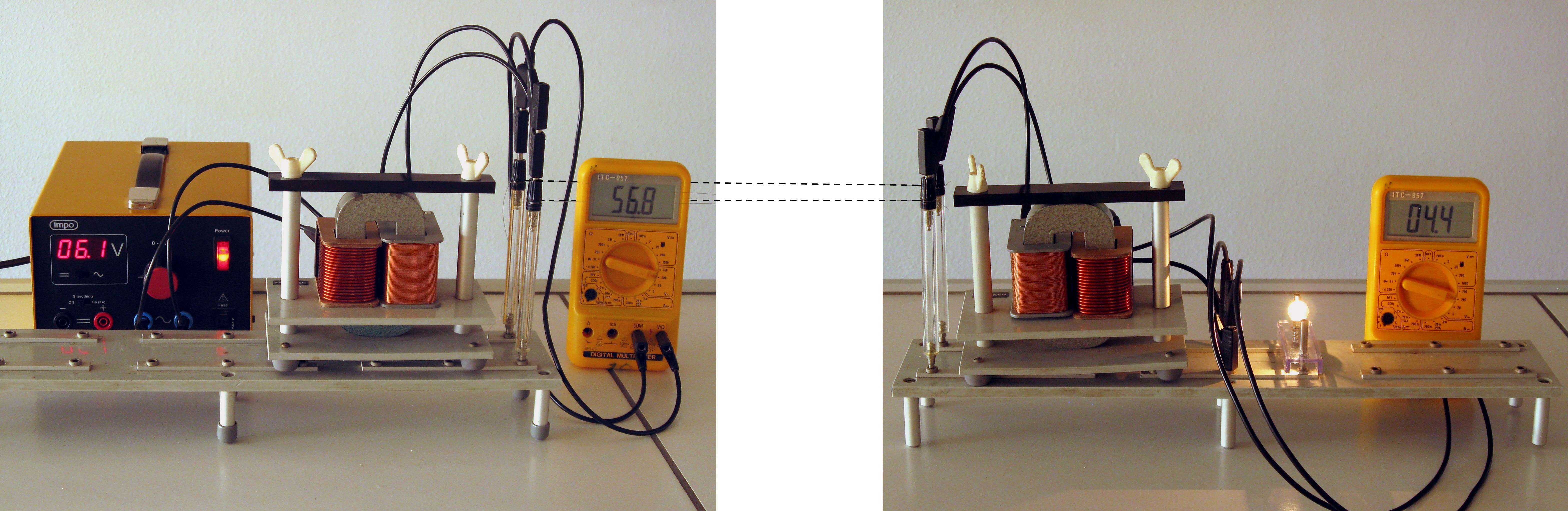
Fig. 16.23 There is light with transformer#
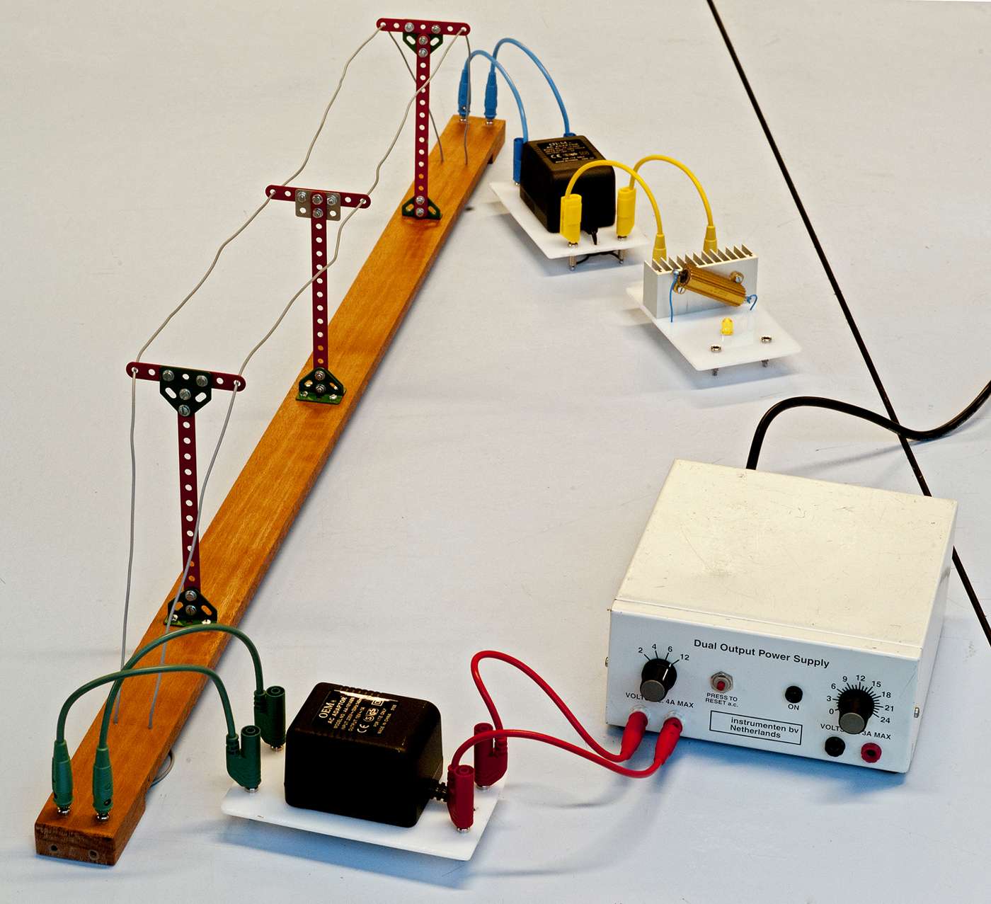
Fig. 16.24 Possible in this way as well#
Procedure#
Turn this demonstration into a story (a detailed example below); .
Energy transport without transformers
On the left is the power station, on the right is a village or town, in between is the transmission line. (You can put a piece of paper on the wires in case students in the back don’t see them). The customer should have 6 volts (depends on the bulb used).
Set the power supply to 6 volts (use the voltage meter), and note that the light is not, or just barely, lit. Measure the voltage at the customer’s premises: far too low!
You can measure the current, calculate the power the customer is getting and the loss rate.
Increase the voltage of the power station until the customer does get 6 V; then the power station delivers … V (measure). The relative loss remains the same.
Problem analysis
The consumer ‘is’ in series with the transmission lines; so the voltage distributes across lines and customer load.
Turn down the source to 6 V. Measure the voltage across both lines and the consumer and find that the total is 6 V.
So the lines have a too much resistance relative to the consumer. The consumer inevitably has a very small resistance because it is a parallel circuit of countless devices and lamps: that gives a very small replacement resistance.
First solution:
Make the resistance of the line smaller. Replace the thin wires with ‘normal’ cords (just connect them in parallel), then the problem is solved. On this scale, it can be done, but in reality it is prohibitively expensive….
Problem analysis
Another way of looking at the problem: If the resistance of the line cannot be easily reduced, then less current must pass through it: The energy loss is \(P_{loss}=I^2R\). However, the transmitted power must remain the same. This is possible if we increase the voltage: The power transported is \(P=UI\).
Second solution
Include the two transformers. The first transforms up and the second transforms down. Set the ‘power plant’ to 6 V again and see that the light does burn properly now.
Measure the voltage at the consumer’s side.
Measure the voltage at the transmission line and see if that matches (approximately) the transformation ratio.
Measure the current through the line (carefully!) and find that it is much smaller than without the transformers, i.e. \(I^2R\) is much smaller.
Measure the voltage ‘across the line’ and find that it is also much smaller. So the voltage drop has become much smaller while the voltage is much larger. (discuss if the voltage is not across the line, where has it gone?) Relatively, that chops double…
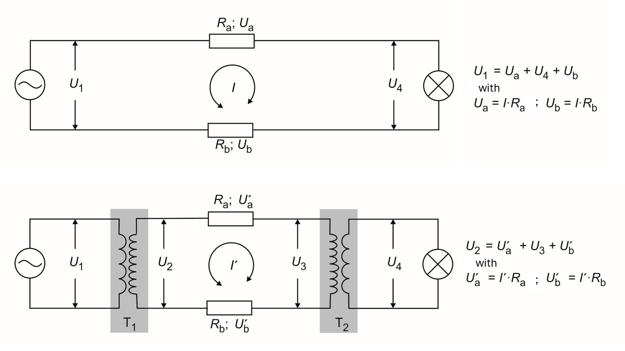
Fig. 16.25 Schematics of both circuits. Top: without the transformers. Bottom: with the transformers.#
Using the scheme above, one can reason that:
and hence the loss of power (heat) is much less when using a transformer.
Finally, discuss the whole circuit again: there are three separate circuits, each with a source and a consumer. If the transformers are ideal, there is only loss in the transmission line.
If required, everything can then be measured and the whole circuit calculated. For this, the best strategy is to draw the whole circuit, put in all the data and then see where to start calculating.
Enhancing your story
To enhance your story you can emphasize that the voltage supply compares to the nearest powerplant, the light at the other side is the school. In some countries (as in the Netherlands), the power lines can be clearly seen, Figure 16.26left. Smaller transformers are often visible in the streets Figure 16.26right, one can refer to these.
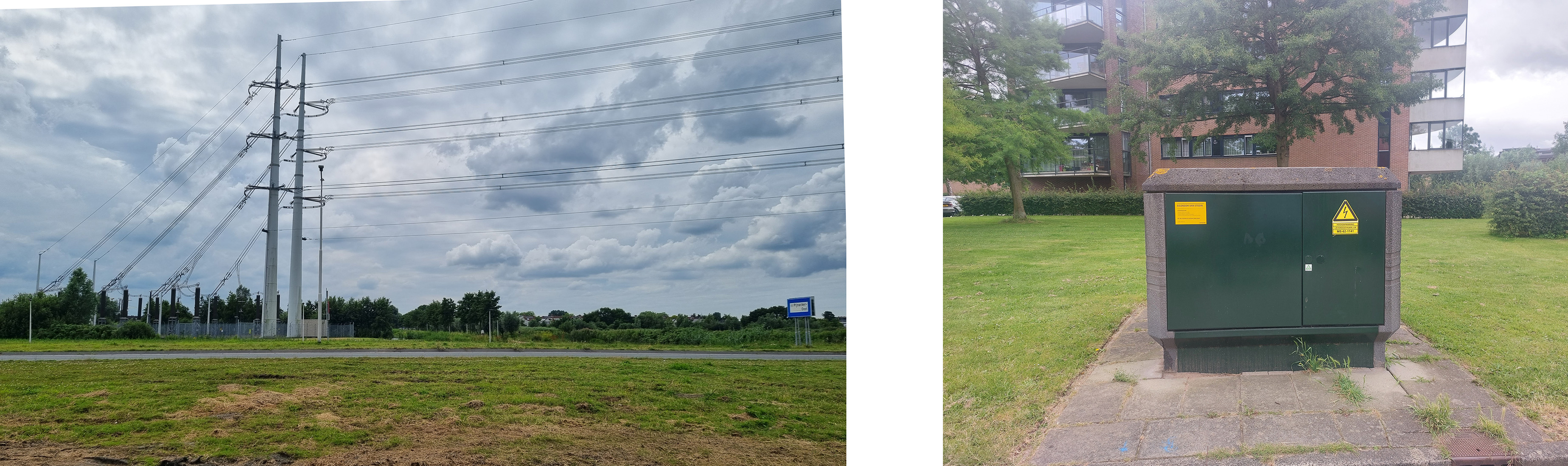
Fig. 16.26 In the Netherlands you often can see the power lines and the transformers near a city (left). There are smaller transformers in each district (right).#
Physics background#
Obviously, the operation of the transformer must be known here, but almost all the basic concepts of electricity automatically come into play. These of course need to be known; the ‘new’ thing about this experiment is mainly the application. As such, the experiment can be a good repetition and integration exercise, especially if it is also calculated through, or if a good calculation example follows.
Tip
If no suitable lamps can be found with the transformers used, a suitable (power) resistor can be used as a load, with a small lamp parallel to it ‘for the eye’.
Some colleagues have a ‘model high voltage’ for this demonstration; see photo 3.
If you only want to do the test qualitatively, for example in an undergraduate classroom, you can start by connecting the light directly to the power station and setting it so that the light burns properly. Then the transmission line in between and then the transformers. Then you don’t have to measure anything at all to still show the principle.
Follow-up#
There can be plenty of further experimentation, e.g. with different loads, different transformation ratios, different lines. Test this prior to the demonstration.
Several educational additions to the described test are possible:
The voltage on the line is dangerously high. Why can you still hold it? But what should you definitely not do? And if you were to ground one point? A treatise on ‘floating’ circuits and isolation transformers: I always have an imaginary 1000 V battery at hand, which I dare to grab on one side…
To make it extra clear that the voltage is quite high, you can connect a 230V/60W lamp; it will then glow weakly. Also note that the lamp at the end of the line will then burn more dimly…
Introduce the following paradox:
According to the formula \(P=I^2R\), the loss decreases because the current decreases when the voltage is transformed upwards. But according to the formula \(P=U^2/R\), the power actually increases. What is happening there? You want to arrive at the following: the voltage ‘on the line’ is the voltage between the two wires, so the ‘high voltage’. The voltage ‘across the line’ is the difference between the beginning and the end of the line, i.e. the voltage loss. Because there is ‘tension across the line’, the tension ‘on the line’ at the end is slightly less than at the beginning.Because it is a series circuit - also with the transformers - the loss percentage can be easily determined by dividing the voltage ‘across the line’ by the voltage ‘on the line’.
It can also be discussed that in practice there is only one line: the ‘return line’ is the earth, whose resistance is negligible. Anyone who still doesn’t think it’s enough, can explain that thanks to the three phases, in practice there is hardly any return current.
Below are the results of measurements of the setup shown in the photos in the book. The high-voltage lines consist of two constant wires (0.20 mm diameter) of 1.2 m in length, each with a resistance of 20 Ω. The powers in different places are indicated in red. In the circuit without transformers the efficiency is 7.7%. With transformers the efficiency is 29%, but this is mainly due to the primitive transformers that have an efficiency of approximately 55%; the loss in the line is minimal. ‘Real’ transformers have an efficiency of around 80%; toroidal transformers up to 90%. Then you have to load them to the maximum, so choose the lamp or load resistor appropriately. But in fact the efficiency of the transformers is not important in this test. As can be seen above, the conclusion remains that the loss in the line is a lot is smaller when using ‘high voltage’, even with the most primitive transformers upright.
Warning
Depending on the power supply and transformers used, voltages of more than 40 V can be put on the line, even hundreds of volts when using mains adapters or bell transformers. So no students near the setup and no more than one hand on the high voltage….