15.16. Strange shadows#
| Author: | Freek Pols & Maarten van Woerkom |
| Time: | 30 minutes |
| Age group: | Grade 8 |
| Concepts: | straight-line propagation, shadow, similar triangles, light, additive mixing of light, primary color, complementary color |
Introduction#
When introducing students to the concepts of light, you can conduct increasingly challenging and interesting light demonstrations with simple tools. Here, we first introduce students to the idea of shadow and half-shadow. Then they are introduced to the ideas of mixing colors which can be done in two different ways: subtractive and additive. When you illuminate an object with colored lights, it is called additive mixing.
Equipment#
A piece of cardboard the size of an A4 sheet with a hole in it
Three lamps on a board.
A panel with three lamps, blue, green, and red (these can be bright LEDs or incandescent bulbs with filters).
In front of the panel is a transparent plexiglass plate with a black cardboard mask that has a square cutout.
Various opaque objects are placed in this cutout during the demonstration. The light from the lamps can thus shine through part of the mask.
The light that passes through the mask hits a screen. The screen is covered with tracing paper, which is translucent white paper.
Part 1#
Preparation#
Connect three lamps in parallel. For convenience, you can use a switch to turn each lamp on/off individually. Ensure there is a 5 to 10 cm space between the lamps.
Fig. 15.41 A schematic of the setup clearly showing the similar triangle.#
Procedure#
You start by showing shadows. Hold a piece of cardboard with a (square) hole above a lamp. On the ceiling, you will see a bright area and a dark area. Shadow is there where light rays can not reach.
Then, ask what determines the size of the illuminated rectangle. The students will quickly suggest that the distance from the cardboard to the lamp is important. With a bit of reasoning, they can also figure out that the distance between the lamp and the ceiling is significant. From there, it is a small step to the formula for the magnification factor (\(N=\frac{L_B}{L_V} = \frac{b}{v} \)).
Fig. 15.42 Core and penumbra of three lamps. Made visible by three lamps, one cardboard with a rectangular hole, and displayed at the classroom’s ceiling.#
Then turn on a second lamp, creating multiple areas on the ceiling, each with a different shade of gray (penumbra). Let students explain how these different areas form. You can link the phenomenon to a stadium where a single person can have multiple shadows at the same time. Let the students predict what will happen if you turn on a third lamp, as shown in Figure 15.42. Now, turn on the third lamp. There will be areas that are completely dark and an area that is very bright. But there will also be intermediate areas that seem gray. These are the penumbra regions.
Part 2#
Fig. 15.43 A schematic of the setup.#
Preparation#
The demonstration should be conducted in a well-darkened room. The better the room is darkened, the more vivid the colors will be. The distance between the panel and the holder, as well as the distance between the holder and the screen, should be determined experimentally. Here are some guidelines:
The distance between the lamps (or LEDs) on the panel is about 10 cm.
The distance between the panel and the holder with the mask is about 20 cm.
The distance between the holder and the screen varies between 0 cm and 50 cm.
Fig. 15.44 The setup.#
Procedure#
This setup can reveal a large number of surprising effects from color mixing. When you place an opaque figure in the mask, it will cause a shadow.
As an example, in Figure 15.45, a small black triangle is placed between the lamps and the screen. Almost the entire screen is illuminated by the three lamps. The combined light from the three lamps is white. However, the black triangle blocks the light from the red lamp higher on the screen. Only blue and green light can reach that area, creating cyan.
In the lower left of the screen, green is blocked, allowing only blue and red to reach that spot; together, they form purple. In the lower right, blue is blocked, allowing only green and red to reach that spot; together, they form yellow.
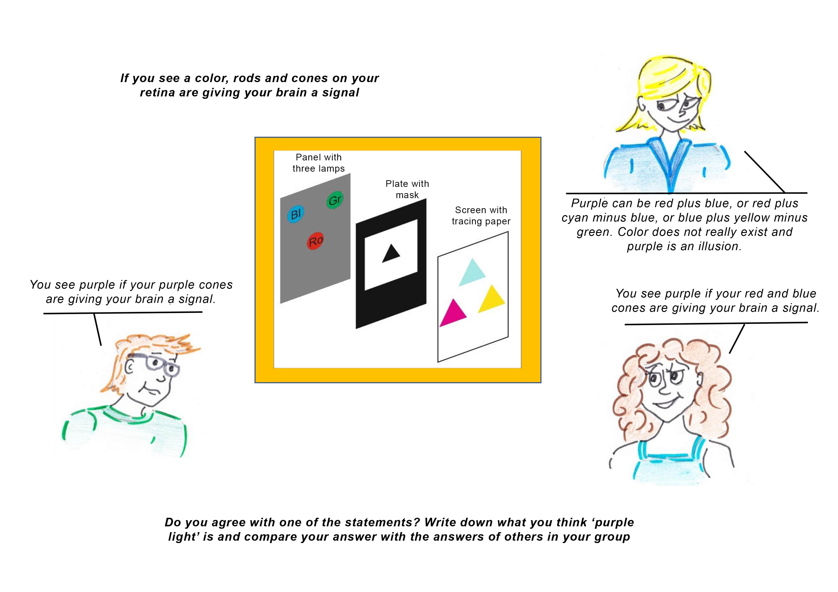
Fig. 15.45 An example to make students think about the additive qualities of light.#
Physics background#
Part 1#
Calculating magnification or the size of a shadow with a point light source is difficult for students. In this demonstration, you develop the formula:
You make it clear that the mentioned variables play a role. You show that the magnification depends on these variables. The formula is also covered in math in the second class, but this often does not coincide with the time it is discussed in physics. Coordination is therefore advisable!
Part 2#
The primary colors in additive mixing are Red, Blue, and Green. These three names are written with a capital letter each. Their complementary colors are Cyan, Yellow, and Magenta. Each of these is made up of two primary colors, which is why they are written with two capital letters. The combination of all three primary colors results in WHIte. Written with three capital letters! In Table 1, you can see the primary colors and their corresponding complementary colors.
Table 1
Primary color |
Complementary color |
Together |
|---|---|---|
Red |
Cyan |
White |
Blue |
Yellow |
White |
Green |
Magenta |
White |
Table 2 shows the results of combining different light sources.
Table 2
Blue + Green |
Cyan |
Red + Green |
Yellow |
Red + Blue |
Magenta |
Red + Blue + Green |
White |
Red + Cyan |
White |
Blue + Yellow |
White |
Green + Magenta |
White |
Various masks are shown in Figure 15.46, with their image on the screen for a nearby screen and a far away screen.
Tip
There are lovely simulations availble on mixing with light, for instance this one from PHET.
In Figure 15.46 1a, the upper half of the cutout is blocked with a piece of black cardboard. The light from the three lamps can only pass through the lower half of the mask, so the lower half of the screen is illuminated by the three lamps, making it white, while the upper half is black. However, because the red lamp is positioned lower, there is an area on the screen where only red light reaches, creating a red strip on the screen.
In Figure 15.46 2a, the lower half of the cutout is blocked. The light from the three lamps can now only pass through the upper half of the mask, illuminating the upper part of the screen white, while the lower part remains black. Since the green and blue lamps are positioned higher, there is an area on the screen where no red light reaches, but green and blue do, creating cyan.
The masks in Figures 15.46 1a and 2a are complementary. If you combine the transparent parts of both, the entire screen becomes white. Similarly, figures 1b and 2b are also complementary. If you combine their illumination, you get a fully white screen. (Since Red and Cyan are complementary.)
In the same way, figures 3a and 4a are complementary, as are figures 3b and 4b. And also figures 5a and 6a, and their corresponding figures 5b and 6b. Increasing the distance between the mask and the screen makes the colored strip wider. This is illustrated in figures 1c through 6c.
The mask in figure 7a is a combination of figures 2a, 4a, and 6a. This can be seen from the colors that appear along the black edges in figure 7b. As the distance between the mask and the screen increases, you get figures like 7c to 7e. The mask in figure 8a is the complement of figure 7a. Hence, its color effects are also complementary.
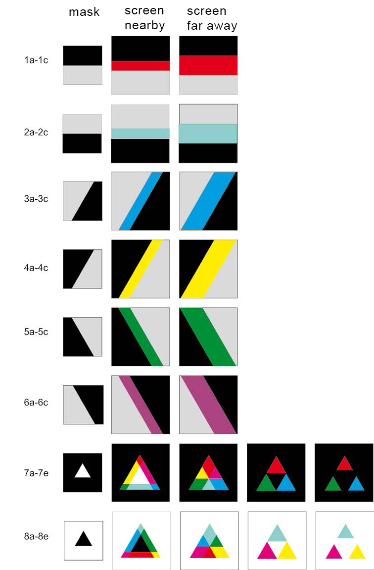
Fig. 15.46 In this series of figures, various masks are shown.#
Follow-up#
The demo Optics with LEDs provides plenty of follow ups.