
6. Sample preparation#
6.1. Sample Preparation#
Sample preparation is a crucial part of biological electron microscopy. Samples have to be prepared for use in vacuum, in most cases they have to be thinned down to an appropriate thickness, they will be irradiated with energetic electrons which will charge and damage the sample, and the elements intrinsically present in biological materials only provide low contrast. All these aspects have to be dealt with when preparing a microscopy sample from live biology. As we have seen in Section 5.8, SEM may allow inspection of (the topography of) an entire specimen which then only requires sputtering or coating with e.g. gold to prevent charging. However, in most cases the aim is to inspect one or multiple sections obtained from a sample, which provides access to the internal biological ultrastructure. The preparation of thin sections is the subject of this chapter and typically involves several distinct steps in a larger sample preparation workflow.
The goal of sample preparation for biological electron microscopy is to preserve the specimen in the native state such that maximum contrast can be obtained with the lowest electron dose. The below video discusses the goal and importance of sample preparation, chemical and cryo-fixation and summarizes further steps sample preparation workflow.
6.2. Preparation workflows for chemical fixation#
The first step in the sample preparation workflow is sample fixation. Proper fixation is key to a successful investigation with electron microscopy. As discussed in the above video, fixation can be done either chemically or by rapid cooling, so called cryo-fixation. Cryo-fixation will be the subject of later paragraphs. Several steps in the chemical fixation have been shown in the video. In general, sample preparation after chemical fixation may involve:
Fixation with aldehydes (glutaraldehyde, para-formaldehyde) followed by dehydration with a graded ethanol series and further fixation with osmium tetroxide
Embedding in plastic, typically an epoxy or an acrylic polymer resin (e.g. Epon, HM20, Durcupan are known resin materials)
Sectioning with a microtome or ultramicrotome using either a glass knife or a diamond knife
Staining or labelling to enhance contrast in the sample
Staining is crucial as the native elements present in the sample (mostly carbohydrates) hardly provide intensity contrast in either back-scatter or transmission detection. Osmium is an important element in the chemical fixation workflow as it is a strong fixative but also functions as a stain providing contrast to membranes and thus allowing visibility of the biological ultrastructure. Further staining, either with additional rounds of osmium or using other metal salts, e.g. with uranyl, lead, neodymium, can be done on the resin block or after sectioning in which case we speak of post-staining. When applying a staining agent to an entire resin block, homogeneous infiltration is a concern that may need additional measures to be taken as an inhomogeneous stain distribution may give rise to artificial contrast variations or low contrast images from sections obtained from deeper in the block. In addition to staining agents, labels such as gold nanoparticles may be added to bind to specific macromolecules or biological structures.
The resin block with embedded biological material typically needs to be trimmed before it can be mounted on the stub of the microtome (see Fig. 6.1). In the microtome, the resin block is sliced over a diamond or glass knife that is mounted on one side of a small bath that can be filled with water. The sliced section thus remains floating on the water where it can be manipulated with an eye lash and picked up with a loop. Alternatively, sections can be cut serially leading to a file of sections, or ribbon (often enhanced by applying some glue to the bottom face of the block), floating on the water surface (see Fig. 6.2). The ribbon(s) can be deposited on a solid substrate placed in the bath beforehand by lowering the water level. Also automated solutions for section pick-up, e.g. with a tape that is continuously pulled through the water bath, have been developed. The substrate onto which sections are mounted should of course be conductive to prevent charging artefacts while imaging (see Section 5.7).
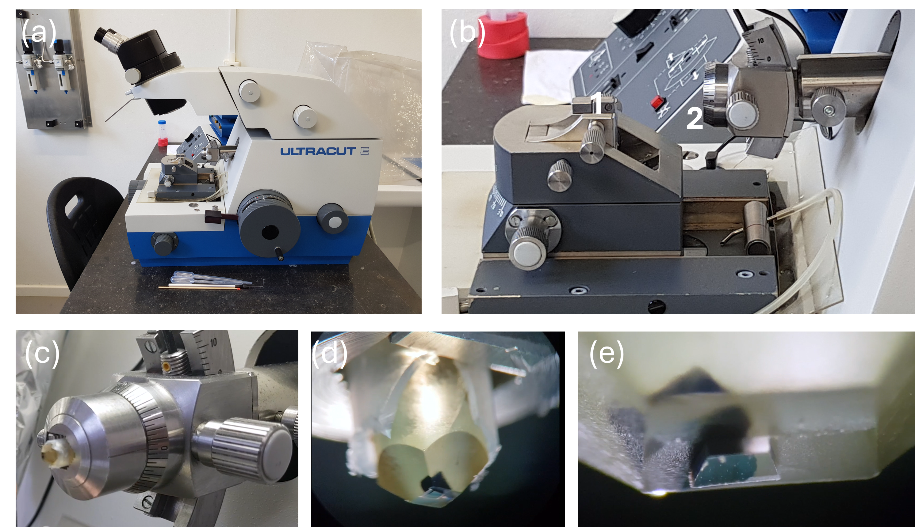
Fig. 6.1 (a, b) Example of a microtome for cutting thin sections from a resin block. 1: position to mount the water boat with knife, 2: stub for holding the resin block. (c) Resin block mounted on the stub. (d, e) Zoom in on a trimmed resin block with embedded biological tissue.#
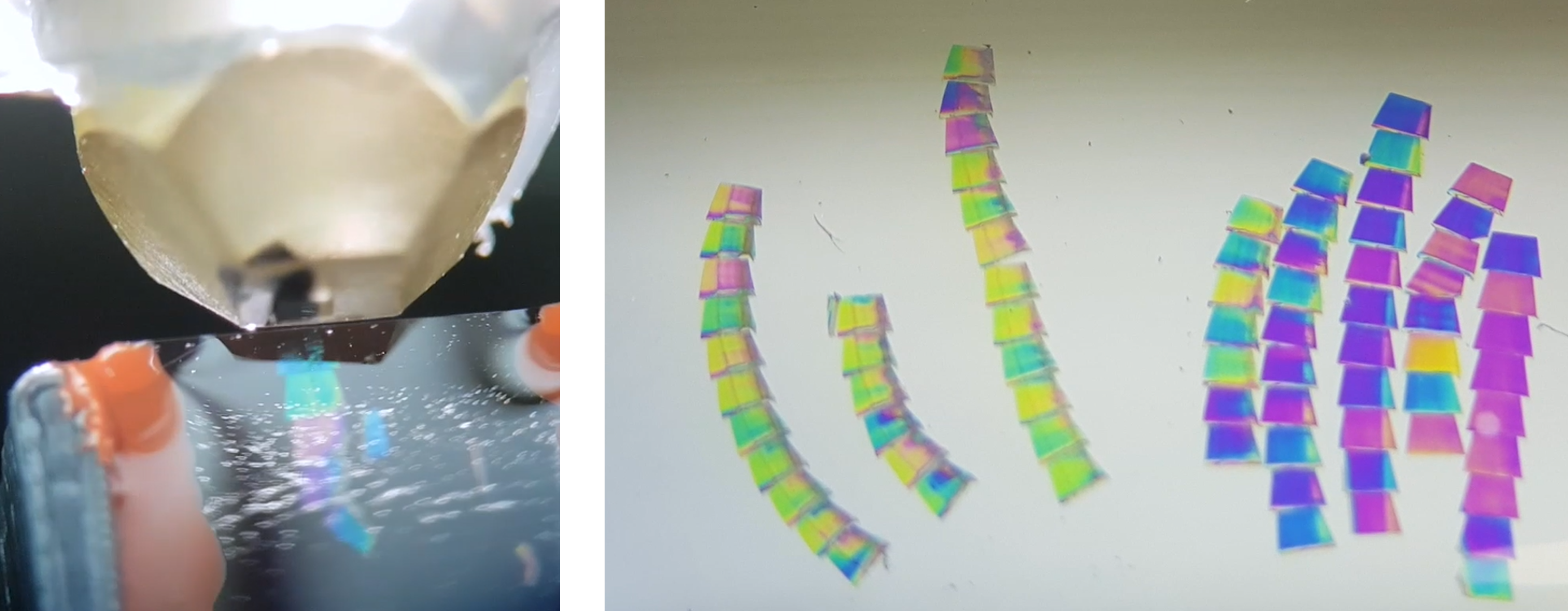
Fig. 6.2 Left: The resin block and the water bath with microtome glass knife edge. The block is pulled over the knife edge each time slicing a thin section. A few sections can be seen floating on the water surface. Right: Ribbons deposited on a solid surface, in this case an indiumtinoxide coated glass slide. The sections colors result from thin film interference and are indicative of the thickness of the sections.#
Many different sample preparations workflows exist depending on the goal of the experiment, the aimed-for microscopy technique, cell or tissue types, and availability or choice of materials. Fixation always needs to be done as is thinning down or sectioning the sample. Embedding needs to be done when using a microtome at room-temperature. Staining is done in most chemical sample preparation workflow and is needed for high resolution unless when using phase contrast imaging. Cryo-fixation can only be done for relatively small samples such as macromolecules, viruses, bacteria, cells, and, with a high-pressure freezer, thin tissues. Larger samples such as organs or organoids, small organisms, and larger tissues including human tissue, can only be fixed by chemical means. However, cryo-fixation can be followed by freeze substitution and further chemical sample preparation steps, and a mild chemical fixation can be followed by cryo-fixation and sectioning under cryogenic conditions. Choices in the sample preparation workflow may also depend on whether electron microscopy is combined with other forms of microscopy on the same sample (correlative microscopy) in order to extract additional or correlative data. Extensive work has been conducted in validating sample preparation workflows for electron microscopy, but care must always be taken to ensure proper fixation and prevent or minimize sample artefacts due to steps in the preparation workflow. Detailed protocols are available in the literature and in dedicated handbooks.
6.3. Cryo-EM Sample Preparation#
Cryo-electron microscopy requires samples to be kept at cryogenic temperatures throughout imaging. The overarching goal is to preserve the biological specimen in a state as close to its native, hydrated condition as possible while making it compatible with the high-vacuum environment of the electron microscope. This is achieved by vitrification, the conversion of liquid water into amorphous (vitreous) ice rather than allowing crystalline ice to form, which would disrupt and destroy biological ultrastructure. Once vitrified, samples must be transferred and handled under liquid nitrogen temperatures at all times to prevent devitrification (recrystallisation) or ice contamination.
The below video discusses the challenges that cryo-EM sample preparation has to address, the phase behaviour of water that makes vitrification necessary, plunge freezing of a thin film on a perforated support grid, and how vitreous ice can be distinguished from crystalline ice in the microscope.
6.3.1. Vitrification#
The phase behaviour of water under rapid cooling is the central physical concept behind cryo-EM sample preparation. As shown in Fig. 6.3, water below 273 K enters a metastable supercooled regime. If cooling is insufficiently fast, ice nucleation occurs spontaneously at the homogeneous nucleation temperature (~232 K at atmospheric pressure), and the sample is destroyed by ice crystal growth. Between roughly 232 K and 136 K lies the so-called no-man’s-land, a temperature range in which crystallisation is kinetically inevitable under slow or moderate cooling rates and in which the liquid phase cannot be studied experimentally. Below approximately 136 K, water can exist as amorphous ice. This can be either low-density amorphous (LDA) or high-density amorphous (HDA) ice, depending on the applied pressure. This glassy state has no long-range order and therefore does not introduce any structural artefacts into the embedded biological material.

Fig. 6.3 Phase diagram of water illustrating the regimes relevant for cryo-EM vitrification. Rapid cooling must traverse the no-man’s-land (232–136 K) before ice nucleation can occur, yielding amorphous (vitreous) ice. LDA: low-density amorphous ice; HDA: high-density amorphous ice. Figure adapted from Debenedetti (2003; DOI 10.1088/0953-8984/15/45/R01). Reproduced under the right to quote; no further use allowed.#
Vitrification requires cooling rates on the order of \(10^4\)–\(10^5\) K s\(^{-1}\). Such rates are achievable only for very thin aqueous layers (typically < 200–300 nm) when using a cryogen with high thermal conductivity, such as liquid ethane or a liquid ethane–propane mixture, cooled to its melting point by liquid nitrogen. Thicker samples cool too slowly, ice crystals form, and the sample is lost. The maximum vitrifiable thickness therefore imposes a fundamental constraint on the accessible sample types and has driven the development of dedicated preparation methods for different specimen categories.
6.3.2. Plunge Freezing#
Plunge freezing is the standard vitrification method for thin specimens such as purified macromolecular complexes, viruses, and indiviudal cells in suspension or grown on TEM support grids. A small volume (2–4 µL) of the sample in aqueous buffer is applied to a support grid. This typically a thin metal mesh with very thin perforated support foil, e.g. a holey carbon or gold grid with holes of ~0.5-2 µm diameter. Excess liquid is the removed by blotting with filter paper so that a thin aqueous film spanning the holes remains. The grid is then plunged rapidly into liquid ethane, achieving vitrification in milliseconds. The entire procedure is performed in a vitrification robot that controls temperature, humidity (to prevent evaporation during blotting), blot force and blot time.
Sample preparation at this stage is critical for downstream data quality. The ice thickness must ideally be matched to the size of the particle of interest. If the ice is too thin and particles are excluded from the holes or are distorted by the air–water interface; if it is too thick and contrast and signal-to-noise are degraded. Surface-active samples or samples that adsorb preferentially to the hydrophobic air–water interface in a preferred orientation require dedicated strategies such functionalised supports to mitigate these effects. Cryoprotectants such as glycerol or trehalose are generally avoided in high-resolution single-particle cryo-EM because they introduce background signal, but may be used for cells or specimens that are otherwise difficult to vitrify.
6.3.3. Cryo-Sectioning (CEMOVIS)#
For specimens that are too thick to be vitrified directly — including intact cells, tissues, and small organisms — an alternative approach is Cryo-Electron Microscopy Of Vitreous Sections (CEMOVIS). Here, the bulk specimen is first vitrified at high pressure using a high-pressure freezer (HPF), which suppresses ice nucleation by transiently applying ~200 MPa of pressure during rapid cooling. At elevated pressure the homogeneous nucleation temperature is depressed (see Fig. 6.3), extending the range of specimen thicknesses and types that can be vitrified without the use of chemical cryo-protectants.
The vitrified block is then transferred to a cryo-ultramicrotome (see Fig. 6.1) where sections of 50–150 nm thickness are cut at temperatures around −140 to −160 °C using a diamond knife. The sections are picked up with an eyelash or ionised air and deposited onto EM grids. CEMOVIS is technically very demanding and needs a high skill level to be succesful. Knife marks, compression artefacts, and crevasses introduced during sectioning are common and can obscure or distort the cellular ultrastructure. Despite these limitations, CEMOVIS remains one of the few techniques that provides access to the interior of intact cells and small tissues at TEM analysis of the near-native state.
6.3.4. Lamella Preparation by Cryo-FIB/SEM#
The most widely adopted method for accessing the interior of cells at cryogenic conditions is now the preparation of cryo-lamellae by cryo-focused ion beam / scanning electron microscopy (cryo-FIB/SEM). Cells or tissue are first vitrified by plunge freezing (for thin samples such as adherent cells) or high-pressure freezing (for thicker specimens). The vitrified sample is then transferred under cryo conditions to the dual-beam FIB/SEM instrument, where a gallium or xenon ion beam is used to mill away material from both sides of a region of interest, thinning it progressively to a lamella of typically 100–300 nm — thin enough for TEM imaging.
The milling is guided in real time by the SEM, which images the sample surface at low voltage without introducing significant radiation damage. A protective platinum or carbon layer is deposited by gas injection on the sample surface before milling to protect the top of the lamella from curtaining artefacts. After milling, the lamella is transferred to a standard EM grid using a cryo-manipulator (lift out), or the grid itself was used as the support from the start (in situ lamella preparation). The resulting lamella can then be imaged in a cryo-TEM, combined with cryo-electron tomography to obtain 3D structural information from within the cell in a close-to-native state.
Cryo-FIB/SEM lamella preparation has become the enabling technology for in situ structural biology, which refers to the determination of macromolecular structures directly within intact cells. The main limitations are throughput (preparing a lamella is a time-consuming, serial process) and the introduction of surface damage by the ion beam (redeposition and amorphisation of a thin surface layer). Sample preparation is still a very much developing field, and automated milling workflows and cryo-plasma-FIB instruments using xenon or argon beams have significantly improved throughput and reduced surface damage.